Monday, September 29, 2008

Just polyhedrals

This weekend was battery box weekend. Or should I say battery polyhedral weekend! You see, the rear cargo area is not a regular shape.

Now I could put a regular shaped box in the cargo area. But I'd be losing a lot of the nooks and crannies to put batteries. So instead of fifteen I could only fit in twelve. To maximize the space I need the "battery polyhedral".


The downside of this design is that it has almost twenty sides including tops and bottoms. And all of them need to be cut to size.


Now cutting this isn't too bad except I don't like butting the joints together. So for extra strength the top and bottom have rabbit joints for extra support. Which explains why it took most of the weekend to cut these pieces.

Next step. Epoxy paint, assembly, and cutting holes for vents and wires.

Oh and one other thing. The battery layout has changed again (hopefully for the last time).

Wednesday, September 24, 2008

Just playing with my rivnuts...see pictures below

Don't get too excited :-0

Since the last post I finished connecting the rear battery rack to the vehicle. Most of the rack is connected by 3/8" bolts and locking nuts directly through the sheet metal. Here's a picture of the bolt through the top.


And here's the bolt, washer, lock washer, and nut on the underside.


This arrangement worked great for the majority of the rack. There were a few places where the rack needed to be connected but was not accessible from under the vehicle.

This is where the rivnuts come in. Rivnuts are blind rivets that accept a bolt. You drill a hole, place the rivnut through the hole, then compress the rivnut around the sheet metal.

This is a picture of an uncompressed (right) and compressed (left) rivnut.


You can see that when compressed the rivnut forms a collar. This collar traps the sheet metal and secures the rivnut. The inside of the rivnut is threaded and accepts the 3/8" bolt.

In case your wondering about the strength of the rivnuts they were originally developed for holding airplanes together!

Sunday, September 21, 2008

Just the rear battery rack

Up to now most of the conversion has centered on the front end of the car. Today I'm going to talk about the back end.

The cargo compartment of the car is going to be used to carry the bulk of the batteries and the battery charger. Here is a picture of the cargo bay prior to the conversion:


This is the cargo bay under the floor:


Of the twenty-four batteries used in the conversion, fifteen will be carried in the rear cargo bay. At ~62lbs per battery that's over 900lbs of batteries.


In order to hold all of these batteries a box needs to be constructed. Supporting the box is a steel platform. I've decided to use 1" x 1", 11ga tubular steel. Here's a picture of the steel pieces cut and in place.


The steel is sitting directly on the sheet metal floor of the cargo bay. Although not shown in the picture the steel is bolted to the sheet metal and sits directly on the frame. Below is the rough location of the frame:


On top of this structure will sit the battery box. The will be constructed of 1/2" thick plywood. The interior will be painted with an epoxy paint to resist fumes released by the batteries during charging. Here's a picture of the floor of the box laid in place.


Under the box and steel supporting structure is where the wires to and from the batteries will exit. It is also where the battery box fumes will be vented. The cavity below the box will be filled with insulation.

Friday, September 19, 2008

Just lesson 2: The Hairball

Continuing on with my the previous discussion, today's topic will expand on some of the safety features in the high voltage wiring system. Below is an expanded schematic of the high voltage system.

One of the safety features in the diagram above is the presence of two contactors in the circuit. Before this ciruit is closed both contactors have to be closed. And for that to happen a specific sequence of events is required. This sequence of events starts with the ignition switch.

Just like in the original vehicle the ignition switch serves the same general functions. The two functions of interest I'll talk about are RUN and START.

RUN is the position the ignition is in after you start your vehicle and it is running normally. START is the position you put the ignition to get the engine cranking.

In order for electricity to get to the motor two contactorshave to be closed. The first contactor is closed when the ignition switch is put into the run position.

The second contactor is controlled by the "Hairball". The Hairball is part of the Zilla controller. One of its main purposes is to interface with other components of the electrical system.

Hairball connection 4 is connected to the start position of the ignition switch. In the original car this ignition position energized the starter motor in order to crank the internal combustion engine and get self sustaining combustion of the engine started. In the electric vehicle this ignition position signals the Hairball to "turn on" the controller and close the second contactor.

Tuesday, September 16, 2008

Just Lesson 1: EV wiring for dummies

Over the weekend I finished as much of the wiring of the high voltage box as I could. Until I mount the controller and build the front battery racks I can't finish the wiring. And I can't do either of those until the adapter arrives and the transmission and motor are installed. I may start on the rear battery racks over the weekend since this is independent of what is going on in the front of the car.

Since I'm just waiting I figured this is a good time to review some EV stuff. So today I'll write "Lesson 1: EV wiring for dummies" (dummies describing the author's level of expertise on this subject, not the readers :-)

Circuitry in the vehicle can basically be divided into two groups: low voltage(12V) and high voltage(144V) . Low voltage circuits are the type of circuits already in the vehicle . They power the lights, instruments, wipers, etc. High voltage circuits are being added and power the electric motor and a few new accessories.

This is a diagram of the main traction circuit.


Let's take a closer look at this circuit. The car I am building is powered by twenty-four 6-volt batteries for a total of 144 volts. The batteries are divided into two packs. Below is the rear battery pack. As the name "pack" implies it consists of more than one battery. The rear pack contains 15 batteries.


All the batteries hooked together can be thought of as one big battery. An analogy would be a flashlight. A small flashlight consists of a single battery with a positive and a negative end. Connect a light bulb between the two and it lights up. If you need more power you get a bigger flashlight which may have two batteries "end to end" (in series). Or you can go even bigger and get one with more batteries. In either case you have multiple smaller batteries that act as one bigger battery.

The Anderson connector is just a special plug that allows the motor to "plug into" the batteries. It is the same as when you plug a lamp into an outlet. It's easier to do that then have to wire the lamp into the fuse box every time you want to connect it.

From the rear battery pack the circuit goes in two directions. There is a negative leg and a positive leg. Eventually the two legs meet up at the motor to complete the circuit and provide power. Let's follow the negative leg first.

The next components in this leg are a fuse and the front battery pack.


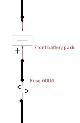
The purpose of the fuse is to protect the wiring and components in case of a short circuit. As eluded to in an earlier post it is analogous to the circuit breakers in your house. If an appliance or lamp in your house short circuits the breaker cuts power to that circuit to prevent further damage.

The fuse is connected to the front battery pack. This is the same as the rear battery pack except only contains nine batteries. Because of weight distribution and size constraints all of the batteries cannot be put together in one location.

Next is the shunt.


It is connected to the rear battery back by a plug. The purpose of the shunt is to allow instrumentation to measure the voltage of the pack and the current going through the traction circuit.

Next in line is the contactor.


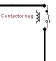
The contactor is essentially and on/off switch. When the switch is open no current flows through the circuit. When closed the circuit is completed. (Actually in my conversion there are two switches that need to be closed to complete the circuit and this is one of those two.)

After the contact comes the "Zilla".


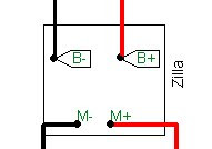
"Zilla" is the brand name of the controller that I am using. The controller is the brains of the EV conversion. At its most basic level a controller regulates the flow of electricity to the motor.

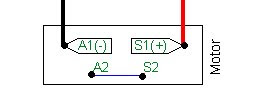
Finally comes the motor. All that electricity has to go somewhere :-)

From the rear battery pack the positive leg of the circuit is essentially the same as the negative leg. The main differences: no more batteries added and no fuse (since the fuse on the negative leg protects the entire circuit).

That's the end of lesson one. I would give out a homework assignment except I'm too lazy to have to grade all of them :-) And remember, all information discussed will be on the final exam!

Friday, September 12, 2008

Just some odds and ends

Today I made some progress on wiring the main high voltage fuse box. This is the box that contains the fuses and relays/contactors that protect the circuitry.

As I've stated before and will probably state again, no matter how prepared you think you are there is always something! Today that something was wire size.

For the high voltage wiring I'm using 2/0 or 00 wire. That's the big wire I showed a picture of last time. Apparently 2/0 electrical wiring and 2/0 welding wire (the type I'm using) are slightly different in size. When I went to the electrical supply store to pick up strain relief fittings (the things that keep the wires from pulling out of the box accidentally) I told them I need to fit 2/0 wire. Of course when I got home the fittings were too small.

So I go back to the electrical store to exchange the fittings. I bring a piece of wire this time :-) Unfortunately they were out of the fitting size I needed. Luckily another electrical supply shop nearby had the correct fitting.

So here is a picture of what I accomplished today.

Wednesday, September 10, 2008

Just breaking in (not breaking) the motor

Today I took the motor for its first run. Technically it is a "stay still" and not a run since the motor stayed in place :-) I guess the proper phrase would be that I took the motor spindle for a run (or at least a fast walk).

Below is a picture of the motor hooked up to a battery charger. The charger is acting as the power source. I was going to take a video. But the spindle turning was exceedingly boring (according to Ari).


The last of the lugs and fuses came in so I started crimping the lugs onto some of the wires. Crimping involves cutting very thick wire, stripping the insulation to expose the ends, sticking the ends into lugs, crushing the lugs to trap wire, then putting heat shrink at the junctions.

Here's the wire so you can get an idea the thickness of 2/0 wire.

Here's a wire with two lugs on the ends. The wire is the big black thing hooked up to the motor.


I also started laying out the components of the high voltage box I spoke about before. I changed the layout a little from prior. This is the new drawing.


And here's the components as I start laying them out.

Monday, September 8, 2008

Just the adapter

That should be, "All I'm waiting for is just the adapter". Thanks to the arrival of the electric motor today.

Thursday, September 4, 2008

Just the batteries...battery...sort of

Even though I have scale pictures for placement of the batteries and components I need to make sure things will fit in real life. It's tough to take accurate measurements in the engine compartment with the engine still in it. With the engine bay empty it's easier.

The engine compartment is not a regular shape. There are nooks and crannies where things once were. There are irregular hoses still in it (like the brake master cylinder and hoses). I want to make sure that I have enough room. So tonight was mock up night.

This is a rough sketch of the engine bay. There are a more nooks and crannies then this shows, but you can get an idea from this.


Based on the fact that the transmission is going back into the same place I have a pretty good idea where the motor will be mounted. Below is where I think it will be.


So now it is time to fit in the batteries. I want to use 24 batteries. I can fit 15 in the cargo area without folding down the seat. So I need to fit 9 in the engine bay. You would think with a big empty engine bay that should be easy :-)

Now before I go any further I should show you a battery...sort of. This is a picture of a regular car battery next to a scale model (note the craftsmanship in the model) of the batteries I will be using.


As you can see from this picture the batteries I'm using are big (slightly less than one foot long, one foot high, and 7" deep). They weigh ~62 lbs each. Here is a preliminary picture of the battery placement.


Looks pretty good, right? So I go into the garage with my handy, dandy life size battery model (a.k.a. ugly white box) to see how this will fit.


Well you remember those nooks and crannies I was talking about? Let's just say that the layout above won't work. So I spend about an hour and a half in the garage with this white box. Moving it this way and that way. It's sort of like a 3-D puzzle. Finally this is what I end up with.


This is still preliminary as I have to wait to install the motor and transmission to be sure that they will actually fit. But I'm pretty confident this layout will work. Of course I was pretty confident the first layout would work too!

One final note. I got news that the motor should be arriving on Monday...by freight...all 180 lbs of it. Hope Ari (my son) does not have a soccer game that night :-)

Wednesday, September 3, 2008

Just preparing again

Now that the car is mostly disassembled I'm waiting for the motor and adapter plate in order to start reassembly. Till they arrive there is lot's of "little stuff" (little meaning not 500lb engine stuff) that needs to be done.

One of the little tasks is putting together an enclosure for the some of the high voltage components in the system. This enclosure serves both as a convenient way to mount the components and as a safety measure.

The components are:

Fuse


The purpose of the fuse is to disable the power and protect the components "plugged" into the battery pack in case of a short circuit or malfunction. The fuse is equivalent to the circuit breakers in a house.

The traction pack is composed of twenty four batteries for a total voltage of 144V. The pack is capable of delivering over 300amps. So this is one big #!& fuse! (For comparison most modern houses are supplied with 120V, 200amp electric service.)

Shunt


In a gas powered car there is instrumentation that informs the driver of the status of various vehicle operating parameters. This includes the fuel gauge (how much fuel is remaining) and the trip computer (how is my gas mileage).

An electric vehicle requires similar instrumentation in order to know how much energy(fuel) is remaining in the batteries and how many miles/watt (miles/gallon) are being used by the vehicle. The shunt is the component that lets that instrumentation "tap" into the battery pack in order to measure some of the above parameters.

Contactor


In a gas powered vehicle turning on the ignition switch starts a series of events that eventually leads to fuel delivery to the engine. Ignition switch closes circuit----relay in starter motor closes---starter motor turns engine---relay in fuel pump closes---fuel pump delivers fuel---combustion occurs in cylinders.

In an electric vehicle the electricity (fuel) is delivered to the motor by closing a switch between the battery and the motor. The contactor is the switch that closes this circuit.

High voltage fuses
Several other components of the vehicle, besides the motor, require electricity. This box also contains the fuses protecting the individual circuits for these components.

Below is a schematic of what it should look like once assembled. Later in the week I'll stop by the electric supply store to pick up parts for the connections.